 TTMER9 - G-PON - Gigabit capable Passive Optical Networks
|
|
GIGABIT
PASSIVE OPTICAL
NETWORKS
(Attention! Material is under construction!)

VOL 2 - 2010.01.11
Copyrigth:
Created by:
Transalted by:
Head of the Laboratory:
1. About the usage of the guide
2.1 Reference model according to the ITU-T Recommendation G.984.1
2.2 Characteristics of the G-PON interface
2.2.1 Functions of the G-PON interface
2.2.2 Downstream frame structure
2.3 Subscriber side terminations of the G-PON (ONU/ONT)
2.4 Passive Optical Network (PON)
3. G-GPON based access network of the laboratory
3.2 Equipments of the G-PON test network
3.2.1 Siemens hiX5750 G-PON OLT equipment
3.2.2 Siemens EM PX network manager
4. Triple-Play in the test network
4.1.1 Establishment of the VLAN interfaces
4.3.3 OLT multicast configuration
4.3.4 ONT side multicast configuration
The following guidance was prepared for laboratory exercise titled "G-PON - Gigabit Passive Optical Networks" (TTMER9) of Infocommunication Laboratory of Faculty of Electrical Engineering. Its primary goal is to teach building of G-PON network of the laboratory and its operation with the help of the tasks given in the measurement instruction (http://alpha.tmit.bme.hu/labor/ttmer9/ttmer9u.rtf) which is for establishing a minimal 3Play service for the subscribers? side.
We assume, that the reader has some practice necessary for the usage of IBM-PC type personal computers, common telecommuncation equipments and LCD televisions, and basic knowledge of computer networks. Some knowledge of telecommunication studies based on TCP/IP (Transmission Control Protocol/Internet Protocol, RFC1180) is also recommended.
Performing laboratory exercises mentioned below is also advantageous for a more complete understanding:
This material can help in topics mentioned below:
G-PON is a representative member of the new generation of access networks, which can give a very high-speed access of gigabit networks with only one optical fiber - distributed with passive optical divisors - typically for carrying TriplePlay services (fast Internet access, telephony, and television).
G-PON may provide an optimal solution for modes of glass fiber distribution (FTTx).
| FTTx | Fiber To The x | |
|---|---|---|
| FTTP: | Premises | - very close to the customer |
| FTTH: | Home | - home of the customer |
| FTTB: | Building | - building or office |
| FTTC: | Curb | - splitter on the street |
| FTTN: | Neighborhood | - near to the above |
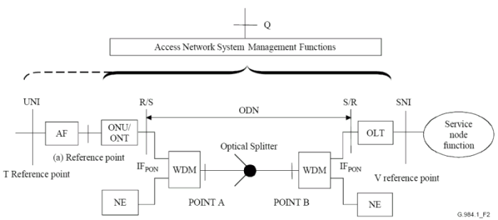
(In contrast with the ADSL reference model, downstream here must be mentioned from right to left.)
Most of the processes of G-PON system interface are located centralized in OLT, and ONTs are only the lenghtened terminals of this.
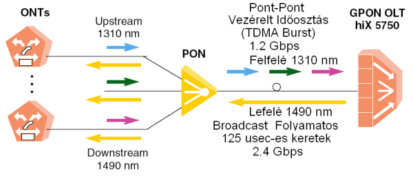
OLT provides structured and quite complex frames (of size of almost 40 kBytes) continuously, in which it informs the individual ONTs, that when and what time they can transmit upstream along the time-axle without disturbing the others.
The most important characteristics of the interface you can see in the table below:
| Characteristic | Upstream | Downstream |
|---|---|---|
| Recommendation | ITU-T G.984.x | |
| Wavelenght | 1310 nm | 1490 nm |
| Wavelenght of the RF/Video WDM | 1550 nm | |
| Bit rate* | 1244.16 Mbps | 2488.32 Mbps |
| Line coding | Simple NRZ, MSB will come earlier | |
| Framing | Ethernet-like bursty GTC | SDH-like continuous, 125 &mu,s frame time |
| Cabling | One optical fibre in mono mode, used in two directions, distributed with divisors (9/125um Single Mode fiber) | |
| Max. cable length | 10..20 kms of physical, 60 kms of principle | |
| Max. delay | 1.5 msec | |
| Optical distribution | tipically 64, max. 128 (principle boundary: 253) | |
* Standard allows other rate - in a pitch, e.g. 622.08 Mbps up
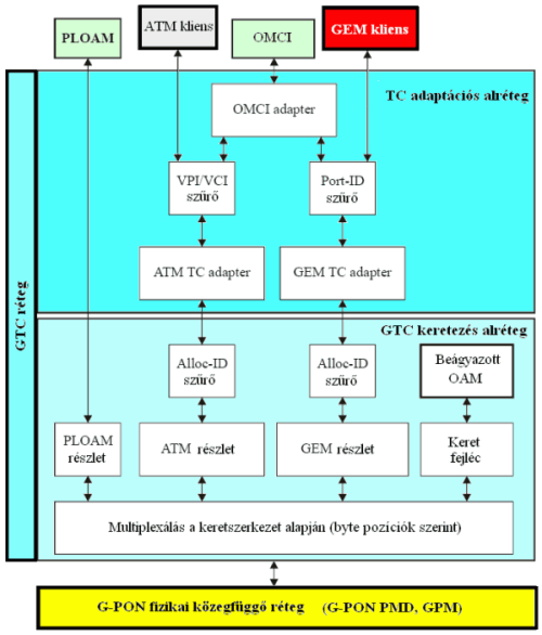
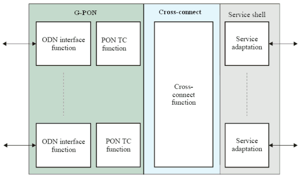
The figure below presents layer model structure of G-PON interface functions.
Frame structure of downstream traffic is described by the ITU-T Recommendation G.984.3, and it can be seen on the following figure.
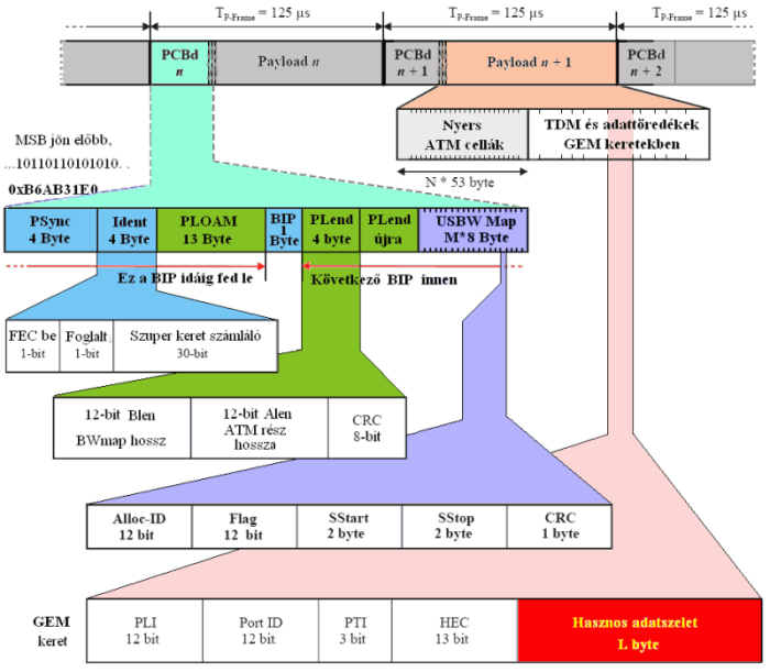
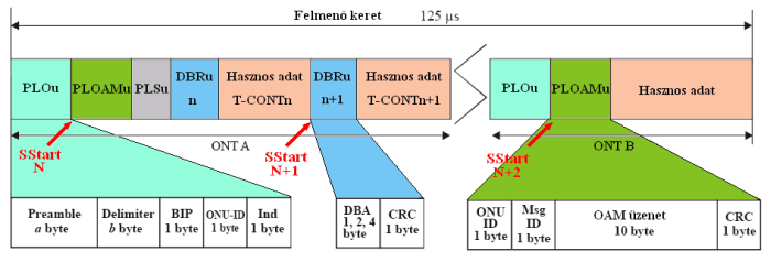
Upstream frames have a length of 125 usec, as the downstream ones, and OLT packs it full with the upstream traffic of ONUs in distribution given in records of the USBWmap.
The frame (T-CONT, Transmission Container) given in an upstream (UpStream, US) direction can be seen on the following figure. We marked also the starting point (SStart) marked by the USBWmap of OLT, where the medium access is provided for ONUs. In our example "ONT A" got a container for even two Alloc Ids (T-CONT), which are covered by a laser by switching on and off.
GPON can provide an extremely flexible and exotic multiplex scheme not only for terminal equipments of the access network, but also for the inherited older equipments as well.
These issues can be tracked on the following figure:
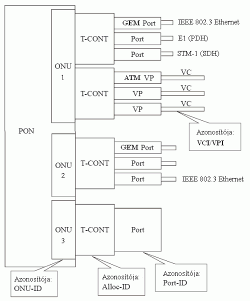
As an Add-Drop Multiplexer (ADM) ONU Nr. 1 can provide:
- 25 Mbps copper ATM access point (ATM T-CONT)
- 155 Mbps optical ATM termination
- 10/100/1000 Mbps Ethernet (GEM T-CONT)
- 2 Mbps E1 interface for exchanges
- 155 Mbps TUG/VC-12 SDH termination for larger exchanges
ONU No. 3 can take, for example, a largest tool in a native GEM port to its TDM backplane.
ONU No.2. could be the ONT in the exercise, which can multiplex VoIP, IPTV and Internet traffics.
2.3 Terminations of the G-PON subscriber side (ONU/ONT)
We summarized types of tools closing the subscriber side of G-PON in the following table:
| SFU Single Family Unit |
SBU/MTU Small Business/Multi-Tenant Unit |
MDU Multi-Dwelling Unit | |
|---|---|---|---|
| ONU | ----- | E1 ATM |
ADSL2+ VDSL2 Gigabit Ethernet |
| ONT | 10/100 Ethernet POTS |
POTS/ISDN BRI Gigabit Ethernet |
POTS 10/100 Ethernet RF overlay |
There are terminals providing services ready for consuming, which can be switched to the user interfaces (UNI) of optical network terminals (ONT), such as a common telecommunication tool (POTS telephone).
For this the tool has to have elements realizing adaptation functions (AF), too. A VoIP signal processor, and an SLIC (Subscriber Line Interface Circuit) allow the access for the telephone, while a small built-in switch may provide the traffic distribution according to VLAN, and forwarding of processable frames by most of the tools without VLAN tags.
The optical network unit (ONU) is just an intermediate network building element, which can be closed by another building element, e.g. DSLAM from the users' side.
So the UNI of the ONU at a T reference point is the SNI of another equipment at the V reference point.
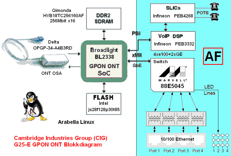
The G25-5 type typical SFU-ONT playing role in the exercise from the outside -
- and its building up from inside. . . (block diagram)
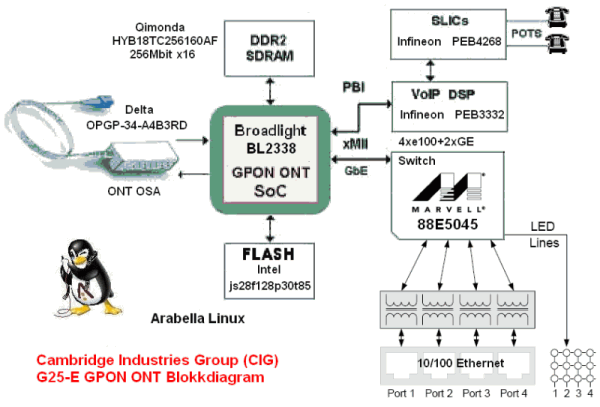
Kernel of ONT is composed by a Broadlight SoC (System on Chip), which realizes interface functions of GPON ONT with the help of a Delta produced OSA (Optical Sub Assembly).
GEM ports suit to a Marvell produced ethernet switching chip on the GMII interface, which is able to make a demultiplexing according to VLAN.
Handling of common telephones made by a VoIP DSP and a SLIC (Subscriber Line Interface Circuit).
Linux can run typically on the processor at the chip. Unit is managed from this place - control and transmission/reception of OAM messages can be executed here. Booting is made from a FLASH memory.
Passive optical networks can provide a cost-effective solution for the high-speed realization of access networks spreading to numerous points at a great distance.
Single-Mode, SM fiber terminations can be multiplied through passive optical divisors with division of signals besides a given loss.
There are two prevalent PON topologies applied:

Similarly to the old bus system cable television topology, here we can ditribute an optical signal to the subscriber terminal from a backbone cable with an attenuation of approximately 10..16 dBs.

The division rate is simmetrically divided here, and fibre is carried to the next point, which is approximately at the same distance, where an equipment, or another divisor can be found.
Combining bus and tree topologies we can achieve a flexible coverage either in the environment of a detached and/or a semi-detached house.
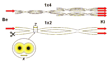
This Fused Biconical Taper divisor, which we can see on the figure above, is applied most frequently in practice.
Attaching (attenuation, division rate) is determined by measurement of fusion (x) and length of the mutual part (z).
The OLT (Optical Line Termination) equipment consists of three main parts, as it can be seen in the ITU-T Recommendation G.984.3:
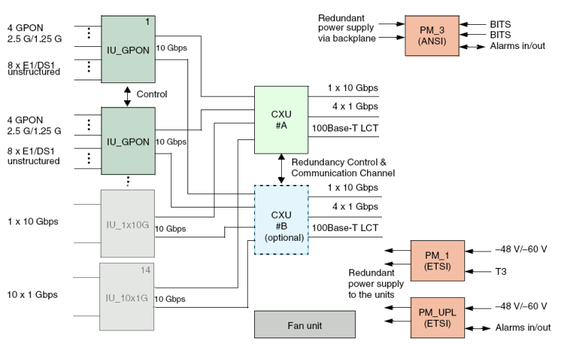
We can examine a realization of OLT at the block diagram of a Siemens hiX5750 G-PON OLT equipment.
Our modern tools, just as OLT, can be managed typically on three ways:
Management of ONTs can be made through OLT, as they were the expanded processes of the OLT.
Diagram of the G-PON (Gigabit-capable Passive Optical Network) subnetwork of telecommunication test network:
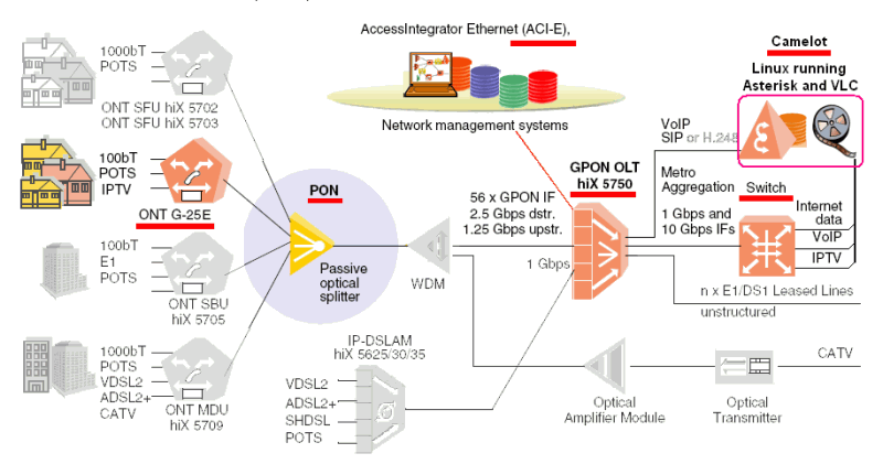
Tools of the network can be found at the laboratory B.212, on the provider's side, in the 19-inch tower, while the subscribers'side is on the laboratory tables of students.
At the bottom of the following figure can the brain of the system be found ? a Siemens hiX5750 G-PON OLT equipment.
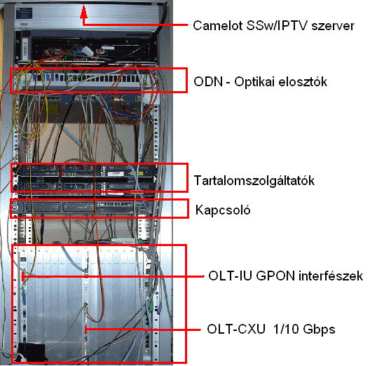
The connector labeled "Console Link" of the CXU serial line is attached to the serial port of the machine at the top of the tower named Camelot (com1, /dev/ttyS0). Serial line parameters are the following: 38400,8,N,1.
The Ethernet port is attached to the network of the University
CLI (Command Line Interface) ) is made with the help of the mincom serial terminal emulator. After giving the root login name and the password determined by the leader of the measurement the prompt of the command explanatory is displayed. Exit from the Minicom: CTRL+A and then Z, and Q.
SWITCH login: root
Password:
SWITCH> en
SWITCH# conf term
SWITCH(config)#
SWITCH(config)#
SWITCH(config)#
Description of the handling surface of the command line in English:
 OLT_hix5750_Command_Line_Interface.pdf
One of the gigabit ports of CXU is attached to the second Ethernet port of the machine named Camelot (an SFP bolster with a copper cable transceiver). The tagged traffic of VLANs of the 3Play service implemented on Camelot goes through this interface towards the OLT.
Services can be fed from another sources, e.g. the switch + server couple located above the OLT.
First optical interface of the IU_GPON card is attached to the divisor one level upper (ODN, a splitter made by ATL), which supplies the ONTs in the laboratories. The 48-volt of power supply (there is no redundancy) is located at the bottom of the tower.
The Ethernet port of CXU labeled "Console Link" is attached to the network of the
University. Its IP address and name are the following: ndev10.tmit.bme.hu, 152.66.246.210.
The ACI-LCT (Access-Integrator Local Craft Terminal) software can theoretically be run on
any of the machines. Here it runs on a machine named pleaides at the top of
the tower, which is available with the help of the VNC.
In the LCT configuration the manager client (Element Manager, EM PX 2.0) and the server run on the same machine. It must be given to the SNMP TRATP host, too.
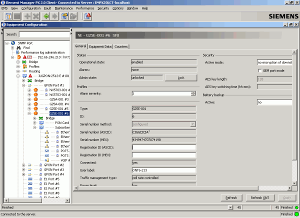
 After starting the EM PX client, we will get a graphic
user surface presenting a tree system, where we can set the characteristics of network
elements on separated sheets. We can get to the configuration sheets on the assigned tool
with the help of the right mouse button, and the "Equipment Configuration".
After starting the EM PX client, we will get a graphic
user surface presenting a tree system, where we can set the characteristics of network
elements on separated sheets. We can get to the configuration sheets on the assigned tool
with the help of the right mouse button, and the "Equipment Configuration".
Putting the OLT equipment into operation, its testing/handling with the help of the EM PX
can be found in the manual mentioned below:
OLT_hix5750_Installation.pdf
The server platform is built around an ASUS P5B Deluxe mainboard. Its technical data are the following:
| Component | Characteristic |
|---|---|
| Mother board | ASUS P5B Deluxe |
| -- Chip set | Intel P965, ICH8R, 1066/800/533 MHz FSB |
| -- Peripheries | 8xUSB 2.0, 1x serial RS232 port (/dev/ttyS0), 2x 1394a FireWire, AD1988B 8 Csat. HD Audio |
| -- LAN | Marvell 88E8001 PCI Gigabit Ethernet (eth1) Marvell 88E8056 PCI-Express Gigabit Ethernet (eth0) |
| -- HDC | Intel 6 xSATA 3 Gb/s port at the south bridge, JMicronR JMB363 PATA and SATA control 1xUDMA 133, 2xSATA RAID (1x external and 1x internal) |
| -- Slots | 1x PCIe x16 (blue), 1x PCIe x4 (x16 black socket), 1x PCIe x1, 3 x PCI |
| CPU | Intel Core2, 2.13 GHz, |
| Memory | 1 Gbyte |
| HDD | SAMSUNG SP2504C, 250 GByte, (/dev/sda) - /dev/sda1 - root file system(/) - /dev/sda3 - video storage (/opt/video) |
 Operation system of the server is the
Debian GNU Linux with 2.6.26 kernel.
This computer, considering its build-up, does not differ essentially from the PCs in the laboratory.
Operation system of the server is the
Debian GNU Linux with 2.6.26 kernel.
This computer, considering its build-up, does not differ essentially from the PCs in the laboratory.
 Video broadcast is provided by the servers of the
VideoLAN VLC
with an open resource code. There is an abundant and up to par documentation on pages of
VideoLAN WiKi .
Video broadcast is provided by the servers of the
VideoLAN VLC
with an open resource code. There is an abundant and up to par documentation on pages of
VideoLAN WiKi .
Video content stored at the server is a legion of MPEG-2 transport streams (TS) recorded from a satellite (DVB-S). Camelot here, as a Playout server, operates either as a content, or a stream provider in the DVB-IP (IP-TV, ETSI TS 102 034) reference model
 Asterix PBX
server with an open resource code provides a VoIP service for the ONT. There is a detailed documentation at the
Asterisk documentation page.
Asterix PBX
server with an open resource code provides a VoIP service for the ONT. There is a detailed documentation at the
Asterisk documentation page.
 The support of WEB based middleware of the AMINO STB from the server side was solved with the help of the Apache
server. There is a detailed description about it on the
Apache documentation pages.
The support of WEB based middleware of the AMINO STB from the server side was solved with the help of the Apache
server. There is a detailed description about it on the
Apache documentation pages.

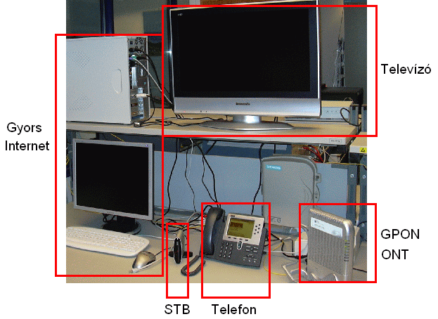
We can see an ONT on the following figure to the right, underneath on the table, a CIG
(Cambridge Industries Group) product, G25-A typed one.
We use in our measurements the more compact, and more up-to-date G25-E type.
Here you can find the English manual for the installation:
ONT_G25E_Installation.pdf
Before we control the existence of services, ONT must be activated by OLT.
- under EM IUGPON/GPON Port #1/ONT tab/Unknown ONT's link
- Select on the basis of the serial number
- Copy to create button
- Click to the Create link, select type, give ID, etc. and finally OK
Measurement command contains the other parameter settings (traffic classes, VLAN ...)
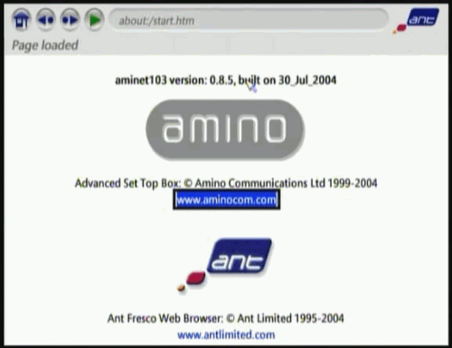
We can see on the previous figure the Amino-making AminNET124 IPTV STB.underneath, on
the centre of the table.
Its function is similar to the function of the indoor satellite units. Besides an
indicental handling of a subscriber card (CAM, Conditional Access Module) another function
is the dechiffring of the data flow containing the selected program/content, on the basis
of a changed key, the video/audio decoding, and display through video/AF/RF outputs.
This tool with its small capabilities can be applied for reception of a standard MPEG-2 coded video content, using either unicast, or multicast transport.
Handling surface is provided by a middleware built onto the web browser of
ANT "Fresco".
Composing the channel list, we can select from the streams giving special URLs, e.g.:
During exercise we can configure the tool in two ways:
Usage of this appliance is very similar to usage of the home entertainment tools.
English manual can help putting this appliance into operation:
STB_AmiNET124_User_Guide.pdf
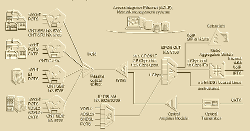
Taking degree of difficulty of this system into consideration, we wanted to build up a minimal service circle on the pattern network, according to the following figure:
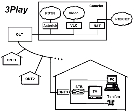
Most of the services were realized in only one platform, on a Linux-based computer named "Camelot". One of its gigabyte ports is connected to the OLT CXU, while another port is connected to the university network.
We can provide a fast Internet connection on the GPON network on NAT-ed VLANs. We will describe in details at Chapter 4.1 its build-up from the creation of VLANs to the usage of iptables tool, and from configuration of ONUs to the testing.
For users the common telephone services is quite complex here. There must be a SIP (Session Initiating Protocol, RFC3261) based VoIP service on the side of the provider for the ONTs, which is solved with the help of an Asterisk PBX. ONTs can solve the conversion with the method demonstrated on the block diagram (DSP+SLIC) under the point 2.3.
Chapter 4.2 describes the installation of Asterisk and its configuration for the achievement of the purpose mentioned above.
IP televisioning is a quite difficult service, which is hard to build up, if we would like to provide a really all-inclusive service with EPG (Electronic Program Guide, an electronic broadcast paper), with multilingual subtitles, VOD (Video On Demand), etc. ...
Our minimal purpose is to build up a television service with a Playout server, that plays films igiven n advance on some of the channels, splicing (loop). Chapter 4.3 will show the installation of VLC, and its application, as a streaming server.
First and foremost we will create three VLAN (Virtual Local Area Network, IEEE 802.1Q-2005 wiki) interfaces for the multiplex transmission of the three services. It means a tagged VLAN on the provider?s side, and everywhere on the transmission way, while the UNI becomes untagged, because most of the user tools do not support tagging.
We use the vconfig tool of the VLAN program packet. (Type apt-get install vlan, if it has not been installed yet.)
#!/bin/sh # - Create HS Internet interface - VLAN 100 vconfig add eth0 100 # - Create VoIp interface - VLAN 101 vconfig add eth0 101 # - Create ipTV interface - VLAN 102 vconfig add eth0 102 |
The example mentioned above creates the VLAN interface of the two other services, too. Existence of the eth0.100, eth0.101, and eth0.102 can be controlled with the help of the ifconfig -a command.
Although the Linux kernel supports the QOS (Quality Of Service), we will not create here traffic classes, because the gigabyte interfaces provide enough bandwidth at the provider?s side.
We can now assign IP addresses to the VLAN interface created like this, and we can set other interface parameters, too. The example mentioned below will set the VLAN interface of all the three services, and bring it to a state ready to operation:
#!/bin/sh # - Configure and bring up HS Internet interface on VLAN 10ö ifconfig eth0.100 10.0.0.1 broadcast 10.0.0.255 netmask 255.255.255.0 up # - Configure and bring up VoIp interface on VLAN 101 ifconfig eth0.101 10.0.4.1 broadcast 10.0.4.255 netmask 255.255.255.0 up # - Configure and bring up ipTV interface - VLAN 102 ifconfig eth0.102 10.0.8.1 broadcast 10.0.8.255 netmask 255.255.255.0 up |
Checking the interface settings:
camelot:~# ifconfig
 . . .
eth0.100  Link encap:Ethernet  HWaddr 00:18:f3:4f:54:47
          inet addr:10.0.0.1  Bcast:10.0.0.255  Mask:255.255.255.0
          inet6 addr: fe80::218:f3ff:fe4f:5447/64 Scope:Link
          UP BROADCAST RUNNING MULTICAST  MTU:1500  Metric:1
          RX packets:0 errors:0 dropped:0 overruns:0 frame:0
          TX packets:6 errors:0 dropped:0 overruns:0 carrier:0
          collisions:0 txqueuelen:0
          RX bytes:0 (0.0 B)  TX bytes:468 (468.0 B)
. . .
|
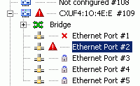
We must check the other side, too, to see, whether the uplink interface of the OLT is ready to operation, or not. The small red triangle means, that there was an alarm on the interface. The small red X means, that the interface is not ready to operation (down). The small lock means an interface administratively out of operation (locked).
It can be done with the help of the EM PX.
It must be checked, and set, if it is necessary:
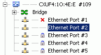
- CXU, Ethernet Port#2, Ethernet tab, unlocked, and up
- CXU, Ethernet Port#2, Bridge tab, PVID 1, and type=uplink
- CXU, Ethernet Port#2, VLAN tab, VLAN 100 HS-Internet (tagged) are existing and added
-- Apply button, if there were any settings
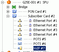
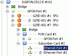
The subscriber Ethernet interface of ONT assigned for a fast Internet access (it is number 4 in our case) must be taken into the 100 VLAN, untagged.
It can be done with the help of the EM PX, too.
It must be checked and set, if it is necessary:
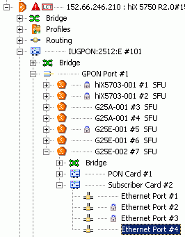
- IUGPON...#101, GPON Port #1, G25E-002#7 SFU, Subscriber Card#2, Ethernet Port#4,
-- Ethernet tab, unlocked, and up
-- Bridge tab, PVID 100, tagging mode: untagged
-- VLAN Assignment tab, VLAN 100 HS-Internet (untagged) are existing and added
-- Apply button, if there were any settings
It is practical to configurate IP ends in case of large mass of users. DHCP (Dynamic Host Configuration Protocol, RFC2131) is just for this purpose.
The dhcpd3 of the ISC (Internet System Consortium) runs on the server. If it has not been installed yet: apt-get install dhcp3-server...
The configuration file contains settings of the DHCP server:
# dhcpd.conf - dhcp3 server configuration file
ddns-update-style none;
option domain-name "tmit.bme.hu";
option domain-name-servers 152.66.246.10, 152.66.146.170;
default-lease-time 600;
max-lease-time 7200;
authoritative;
#Hs Internet
subnet 10.0.0.0 netmask 255.255.255.0 {
  range 10.0.0.100 10.0.0.200;
  option broadcast-address 10.0.0.255;
  option routers 10.0.0.1;
}
#VoIP
subnet 10.0.4.0 netmask 255.255.255.0 {
  range 10.0.4.100 10.0.4.200;
  option broadcast-address 10.0.4.255;
  option routers 10.0.4.1;
}
#IpTV
subnet 10.0.8.0 netmask 255.255.255.0 {
  range 10.0.8.100 10.0.8.200;
  option broadcast-address 10.0.8.255;
  option routers 10.0.8.1;
}
|
We gave here the shared address domains to the interfaces holding the three service circles.
Starting of the DHCP server will be happen with the help of the command mentioned below on the given interfaces:
#!/bin/sh # - Start up DHCP service on the specified interfaces dhcpd3 -cf ./dhcpd.conf eth0.100 eth0.101 eth0.102 |
As the server starts to distributing addresses to the clients, they will be recorded to the /var/lib/dhcp3/dhcpd.leases file. One of the conditions of the correct operation of a given client can be controlled here at the same time.
The IP connection is ready to operation for a client, theoretically. It can be controlled with the help of the tool from the ping command line (for testing the network connection ICMP, namely Internet Control Message Protocol, echo-request/reply messages, RFC792), or with the help of the WEB browser, if we give the 10.0.0.1, as a destination address.
If there is no connection, we must check the following:
With the help of the NAT (Network Address Translation, RFC1631) process it can be solved, that clients may access not only the provider (Camelot), but also the Internet behind it. The newest Debian distributions contain Linux Firewall components from another basis, which contains filtering and address translation.
At creation of the NAT, and setting of an incidental firewall we can use the iptables tool. At starting it applies the rules in the /var/lib/iptables/active file automatically. Refreshing of the setting will be happen with the help of the /etc/init.d/iptables start command. The basic configuration contains only filterings according to the issues mentioned below:
# NAT *nat :PREROUTING ACCEPT [66:9560] :POSTROUTING ACCEPT [2:1113] :OUTPUT ACCEPT [2:1113] COMMIT # Mangling *mangle :PREROUTING ACCEPT [116:16732] :INPUT ACCEPT [72:11425] :FORWARD ACCEPT [0:0] :OUTPUT ACCEPT [30:4702] :POSTROUTING ACCEPT [30:4702] COMMIT # Filtering *filter :OUTPUT ACCEPT [0:0] :FORWARD ACCEPT [0:0] :INPUT DROP [0:0] -A INPUT -s 127.0.0.1 -j ACCEPT -A INPUT -s 152.66.246.0/24 -j ACCEPT -A INPUT -s 152.66.247.0/24 -j ACCEPT -A INPUT -s 10.0.0.0/8 -j ACCEPT # Debian Updates -A INPUT -s 195.228.252.133 -j ACCEPT -A INPUT -s 195.228.252.132 -j ACCEPT -A INPUT -s 194.109.137.218 -j ACCEPT -A INPUT -s 128.101.80.133 -j ACCEPT -A INPUT -s 82.94.249.158 -j ACCEPT COMMIT |
It can be seen, that many of the rule tables are empty. If we would like clients to access to the Internet, we must appropriately fill the "POSTROUTING ACCEPT" table of the NAT section with the help of the iptables tool.
Translate all the addresses of the outgoing packet resources on the eth1 to your own interface address, and translate the answers going back to the translated packets ont he eth0 to your own resource address according to the issues below:
#!/bin/sh # - Setup NAT, and open the firewall for the translated stuff iptables -t nat -A POSTROUTING -o eth1 -j SNAT --to-source 152.66.246.101 iptables -t nat -A POSTROUTING -s 10.0.0.0/24 -o eth0 -j SNAT --to-source 10.0.0.1 iptables -t filter -A INPUT -s 10.0.0.0/24 -j ACCEPT |
The last step necessary to the operation of the NAT is the permission of a kernel level route selection, packet forwarding. As a constant setting, it is the following in the older Debian systems in the /etc/network/options file:
/etc/network/options: ip_forward=yes |
While in the case of the newer ones it must be given in /etc/sysctl.conf according to the following:
/etc/sysctl.conf: net.ipv4.ip_forward=1 |
In the case of almost all the Linuxes it must be given from the command line, or script:
#!/bin/sh echo 1 > /proc/sys/net/ipv4/ip_forward |
ONTs installed for the test network (Siemens, CiG products) SIP (Session Initiating Protocol, RFC3261), MGCP (Media Gateway Control Protocol, RFC3435), and/or MEGACO (RFC3015, just like the ITU-T Rec. H.248) support protocols for the realization of telephone services.
We apply here in the network the SÍP based solution with running of the Asterisk PBX, which will be later applicable to the access to the other elements of the pattern network.
OLT is quite transparent here - it provides only the creation of the T-CONT with an appropriate bandwidth for the VoIP RTP and its signal traffic.
Since there are common analogue telecommunication tools connected to the ONTs, they have an important role - they have to implementate the SÍP protocol, and suit to the POTS interface.
Coverage of the reference provider (refprovider) and distribution of the telephone numbers is shown in the table below:
| Calling number | Location | ONT | Port | IP Address | Context |
|---|---|---|---|---|---|
| 100 | IB212b or teacher | Native IP Phone LINKSYS SPA942 |
(LAN) | 152.66.246.162 | refprovider |
| 200 | IB212a tower | No.1,S/N:07074126 | POTS1 | 10.0.4.10 | refprovider |
| 201 | IB212a tower | No.1,S/N:07074126 | POTS2 | 10.0.4.10 | refprovider |
| 108 | Right time | --- | --- | --- | refprovider |
| 4242 | Answering machine | --- | --- | --- | refprovider |
For the development of the quite minimal reference service we changed the newly installed Asterisk configuration according to the following:
/etc/asterisk/sip.conf - In which after giving the usual parameters, we take the three ends (100,200,201) to the refprovider circle.
#------------------------------------ [general] context=default allowoverlap=no bindport=5060 bindaddr=0.0.0.0 srvlookup=yes disallow=all allow=ulaw [authentication] [100] type=peer host=dynamic secret=100 context=refprovider mailbox=100@default [200] type=peer host=dynamic secret=200 context=refprovider mailbox=200@default [201] type=peer host=dynamic secret=201 context=refprovider mailbox=201@default |
[general]
static=yes
writeprotect=no
clearglobalvars=no

[globals]
CONSOLE=Console/dsp    ; Console interface for demo
IAXINFO=guest          ; IAXtel username/password
TRUNK=Zap/G2           ; Trunk interface
TRUNKMSD=1             ; MSD digits to strip (usually 1 or 0)

[macro-phone]
exten => s,1,Dial(SIP/${MACRO_EXTEN},25)
exten => s,n,Goto(${DIALSTATUS},1)
exten => ANSWER,1,Hangup
exten => CANCEL,1,Hangup
exten => NOANSWER,1,Voicemail(${MACRO_EXTEN}@default,u)
exten => BUSY,1,Voicemail(${MACRO_EXTEN}@default,b)
exten => CONGESTION,1,Voicemail(${MACRO_EXTEN}@default,b)
exten => CHANUNAVAIL,1,Voicemail(${MACRO_EXTEN}@default,u)
exten => a,1,VoicemailMain(${MACRO_EXTEN}@default)

[refstations]

exten => 100,1,Macro(phone)
exten => 200,1,Macro(phone)
exten => 201,1,Macro(phone)
exten => 4242,1,VoicemailMain(default)
exten => 108,1,SayUnixTime()

[refprovider]
include => refstations
|
Finally in the /etc/asterisk/voicemail.conf - we can assign answering machines to
the stations. We won?t bother the other 58 configuration files. 
we can assign answering machines to the stations. We won?t bother the other 58 configuration files.
#!/bin/sh # - Startup Asterisk PBX, and pass the firewall /etc/init.d/asterisk start iptables -t filter -A INPUT -s 10.0.4.0/24 -j ACCEPT |
We can access to the operator console of the Asterisk with the help of the asterisk -vvvcr command with a large verbosity. If the too much information is disturbing, verbosity can be taken back from the console.
Some useful console commands:
| core set verbose 1 | Setting verbosity to 1 |
| sip show peers | List of registrated SIP ends |
| sip show peer 200 | Detailed data of ends 200 |
| sip show channels | List of living channels |
| sip show settings | Viewing of SIP settings |
| console dial 100@refprovider | Calling initation from the console to the refprovider 100 |
| console hangup | Hangup from the console |
| quit | Quitting from the console connection (Asterisk continues running) |
Since the OLT is quite transparent considering the VoIP service, excepting distribution of information, it is enough to control the VLAN connection towards the service, and the settings of the SIP profile.
These issues can be done with the help of the EM PX.
It must be checked, and set, if it is necessary:
- CXU, Ethernet Port#2, Ethernet tab, unlocked, and up
- CXU, Ethernet Port#2, Bridge tab, PVID 1, and type=uplink
- CXU, Ethernet Port#2, VLAN tab, VLAN 101 VoIP (tagged) is existing, and added
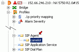
It must be checked, and if it is necessary, a SIP profile named Camelot must be generated:
- 152.66.246.210:hiX5750, Profiles, SIP Agent
-- Selecting camelot and checking IP parameters
--- 10.0.4.1 for every services and 5060 SIP service port
-- or right mouse button on SIP Agent and generate with the "New SIP Agent Profile", if it does not exist.
As the most difficult part of the work is made by the ONT at the subscriber side, the configuration is more complex, too. We have to be sure, that we have enough bandwidth at our disposal for transmission of RTP packets and the signal in the T-CONT assigned for the VoIP.
It must be checked, and set, if it is necessary:
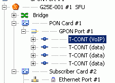
- IUGPON...#101, GPON Port #1, G25E-002#1 SFU, PON Card#1, GPON Port#1, T-CONT (VoIP)
-- T-CONT tab, Upstream bandwidth - Fixed (kbps) values must be selected to be large enough
( Nx64kbps+RTP overhead+signaling)
-- Apply button
Signal protocol must be set (it is the SIP in our case)
- IUGPON...#101, GPON Port #1, G25E-002#1 SFU, Subscriber Card#2
-- VoIP tab, Signaling protocol: SIP. . . (or "Retrieve configuration profile" button)
-- Apply button
VoIP traffic must be directeded to the assigned VLAN and the connection must be checked.
- IUGPON...#101, GPON Port #1, G25E-002#1 SFU, Subscriber Card#2, VoIP#7,
-- VoIP tab, IP addresses, mask all right, answer to ping, trace-route
-- TCP/UDP tab, 5060-as SIP port is added
-- Bridge tab, PVID 101
-- VLAN Assignment tab, VLAN 101 VoIP (tagged) is existing and added.
-- Use the Apply button, if there were any settings
-- Connection must be checek from the server (ping):
camelot:~# ping 10.0.4.10 PING 10.0.4.10 (10.0.4.10) 56(84) bytes of data. 64 bytes from 10.0.4.10: icmp_seq=1 ttl=64 time=2.63 ms 64 bytes from 10.0.4.10: icmp_seq=2 ttl=64 time=2.29 ms 64 bytes from 10.0.4.10: icmp_seq=3 ttl=64 time=2.34 ms ^C --- 10.0.4.10 ping statistics --- 3 packets transmitted, 3 received, 0% packet loss, time 2008ms rtt min/avg/max/mdev = 2.293/2.424/2.637/0.161 ms |
Finally we have to give the added SIP proxy server by POTS ends, and the terminal identifiers:
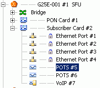
- IUGPON...#101, GPON Port #1, G25E-002#1 SFU, Subscriber Card#2, POTS#5,
-- SIP tab, User part address ... Every of them till the user password to 200, Profiles -
Agent: Camelot
-- Apply button
After restarting ONT we should get a dial sound, if we pick up the receiver, and we should be able to call the right time service at telephone number 108.
For the error searching and prevention we can use commands of the Asterisk console, and the tcpdump tool (tcpdump -i eth0.101 -fAs 1024 for the SIP messages).
Building up a sterling worth IP television service exceeds both our financial and technical possibilities. It is not necessary for demonstrating the possibilities of the access network to install a head station, to get licences of coded programs, and to develop a whole infrastructure, including hardware transcoders.
Thus, in a minimal service circle there are NO:
- VoD, Video on Demand
- EPG, Electronic Programme Guide (ETSI ETS 300 707)
- SAP, Session Announcement Protocol
(RFC2974) - for the announcement of multicast sources
- All inclusicve IGMP (Internet Group Management, RFC2236) outbound
- and even CA, Conditional Access (ITU-R BT.810) - nor subscriber card acccess ...
But there are movie display to the televisions at the measurement places with a VLC streamer, and a web surface provided by an Apache server.
The VLC tool executed in more issues can play in a loop MPEG-2 transport processions recorded previously from a satellite (MPEG-TS " ISO/IEC 13818-1, and ITU-T Rec. H.222) in a multicast transmission mode.
We can provide a fresh channel list at the web surface with URLs belonging to the existing stream.
Since we issue the service on the previously generated (4.1.1.1) VLAN 102 interface (4.1.1.1), we should inform the route selector of Camelot as well, that we would ask the multicast address domain used for spreading to this interface.
#!/bin/sh # - Include VLAN 102 in this multicast range, and pass the firewall route add -net 224.0.0.0 netmask 240.0.0.0 dev eth0.102 iptables -t filter -A INPUT -s 10.0.8.0/24 -j ACCEPT iptables -t filter -A INPUT -s 224.0.0.0/8 -j ACCEPT |
We can check the routing talbe with the help of the netstat -r command as it can be seen as follows:
camelot:~# netstat -r Kernel IP routing table Destination Gateway Genmask Flags MSS Window irtt Iface 10.0.4.0 * 255.255.255.0 U 0 0 0 eth0.101 10.0.0.0 * 255.255.255.0 U 0 0 0 eth0.100 192.168.1.0 * 255.255.255.0 U 0 0 0 eth0 localnet * 255.255.255.0 U 0 0 0 eth1 10.0.8.0 * 255.255.255.0 U 0 0 0 eth0.102 224.0.0.0 * 240.0.0.0 U 0 0 0 eth0.102 default cisco.tmit.bme. 0.0.0.0 UG 0 0 0 eth1 |
Tip: application of ping to the address 24.0.0.1. All the existing multicast clients will answer to it.
The VideoLAN VLC tool with an open resource code is applicable for issuing a moving picture and sound content with an appropiate timing and appropriate parametering, as a multicast stream:
#!/bin/sh
# - Playout a movie in loop, and advertise itself. . .
vlc -v0 \
/opt/video/SDTV/Charlie_and_the_Chocolate_Factory.mpg \
-L                         \
-I dummy                   \
--repeat                   \
--sout '#duplicate{        \
 dst=standard{             \
   access=udp,             \
   mux=ts,                 \
   dst=239.255.12.101:1234,\
   sap,                    \
   name="Charlie_and_the_Chocolate_Factory", \
   ttl=2}}'  &
|
where:
If the VLC has started without any errors, the successful spread can be controlled with the help of the tcpdump, and ifconfig commands ("tcpdump -i eth0.102" may show a strong UDP traffic, and in case of "ifconfig eth0.102" growing of TX bytes shows it, too).
Video streams played out by the refprovider at the Camelot:
| Charlie_and_the_Chocolate_Factory.mpg | 239.255.12.101:1234 |
| Minimax_October_29_16_56_56.mpg | 239.255.12.102:1234 |
| Madagascar-TAQUILLA.mpg | 239.255.12.103:1234 |
| Around_The_World_In_80_Days.mpg | 239.255.12.104:1234 |
| Star_Wars3-TAQUILLA.mpg | 239.255.12.105:1234 |
Script detail, which can start it:
#!/bin/sh
# - Play out function
PlayOut ()
{
echo   - playing $1
vlc -v0 /opt/video/SDTV/$1 -L -I dummy --repeat --sout \#duplicate\{ \
    dst=standard\{access=udp,mux=ts,dst=$2,sap,name="$1",ttl=2\}\}   \
    1>/dev/null 2>/dev/null &
}
# - Play out MPEG-2 files from the repository
PlayOut Charlie_and_the_Chocolate_Factory.mpg   239.255.12.101:1234
PlayOut Minimax_October_29_16_56_56.mpg         239.255.12.102:1234
PlayOut Madagascar-TAQUILLA.mpg                 239.255.12.103:1234
PlayOut Around_The_World_In_80_Days.mpg         239.255.12.104:1234
PlayOut Star_Wars3-TAQUILLA.mpg                 239.255.12.105:1234
echo ---- Done
|
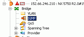
In case of OLT there could be a possibility for the frequently applied IGMP snooping (switching of a multicast traffic with observation of the IGMP report signals), or setting of a Proxy (an IGMP router operates as an end interface) but if they are strongly beta versions, we will only execute the setting of the simple switching. It can be done with the help of the EM PX.
It must be controlled, and set, if it is necessary:
- CXU, Bridge, IGMP, Mode: VLAN switching
- CXU, Ethernet Port#2, Ethernet tab, unlocked, and up
- CXU, Ethernet Port#2, Bridge tab, PVID 1, and type=uplink
- CXU, Ethernet Port#2, VLAN tab, VLAN 102 IpTV (tagged) is existing and added
-- Apply button, if there were any settings
We can control, and create IGMP based IpTV providers, too:
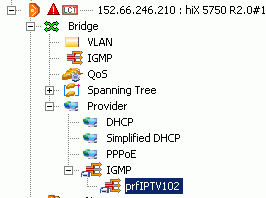
- We should give the adresses of Camelot at the IGMP provider tab,
- At VLAN tab they have to be put to the 102 (untagged)
Content service is made in packet built to the IGMP groups.
- New packages can be prepred under the Packages tab
- New IGMP groups can be made under the Groups tab
/p>
4.3.4 Multicast configuration on the ONT side
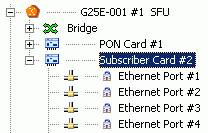
Since we have chosen the VLAN based switch, we should put the subscriber Ethernet interface assigned for a multicast IPTV connection of the ONT (it is number 1 in our case) to the VLAN 102, untagged.
It can be done with the help of the EM PX, according to the following:
It must be checked, and set, if it is necessary:
- IUGPON...#101, GPON Port #1, G25E-002#7 SFU, Subscriber Card#2, Ethernet Port#1,
-- Ethernet tab, unlocked, and up
-- Bridge tab, PVID 102, tagging mode: untagged
-- VLAN Assignment tab, VLAN 102 IpTV (untagged) is existing and added
-- IGMP tab, there is at least one subscriber packet admitted to the list controlling the access (ACL)
-- Apply button, if there were any settings
Configuration of the Set Top Box could be solved with the help of the IR keyboard,too, according to its description, but since our subscribers do not want to execute difficult series of operations, and our installers have not enough qualification to do it, we will manage the channel list from the server with the help of the Telnet, and we will use the web surface provided by the Apache server.
After connecting and switching of STB it have to get an IP address from our DHCP server. We can check it with viewing the lease list:
camelot:~# cat /var/lib/dhcp3/dhcpd.leases
# The format of this file is documented in the dhcpd.leases(5) manual page.
# This lease file was written by isc-dhcp-V3.1.1
. . .
lease 10.0.8.102 {
  starts 4 2010/02/04 14:22:39;
  ends 4 2010/02/04 16:22:39;
  cltt 4 2010/02/04 14:22:39;
  binding state active;
  next binding state free;
  hardware ethernet 00:02:02:0b:68:4a;
  uid "\001\000\002\002\013hJ";
}
|
On the basis of its physical (MAC) address we can determine, where the tool is (it is placed on record of S/N and MAC at the time of installation). We can control with the help of the ping command, whether the tool is ready to operation according to its state, or not.
Control of the tool from the side of the server can be done simply through a Telnet connection, with the help of a command line interface. This latter is a Linux shell, with a BusyBox command collection, and with some specific applications
camelot:~# telnet 10.0.8.102 Trying 10.0.8.102... Connected to 10.0.8.102. Escape character is '^]'. AMINET login: root Password: [root@AMINET]# |
Beyond commands built into the shell, there can be used a narrow circle of the usual Linux applications (stored version).
The modified configuration files can be dragged down from the server with the help of the wget tool. Here can the refreshment of the channel be seen, as an example:
[root@AMINET]# cd /mnt/nv [root@AMINET]# cp chnls.txt chnls.old [root@AMINET]# wget http://10.0.8.1/chnls.txt Connecting to 10.0.8.1[10.0.8.1]:80 chnls.txt 100% |*****************************| 320 00:00 ETA [root@AMINET]# |
A supposed channel list file given by the refprovider to the video streams (/mnt/nv/chnls.txt on the STB)
# Amino Fresco Channels File # Written Tue Nov 30 00:54:28 1999 _version: 1 00: file://management.html 01: http://10.0.8.1/index.html 02: igmp://239.255.12.101:1234 03: igmp://239.255.12.102:1234 04: igmp://239.255.12.103:1234 05: igmp://239.255.12.104:1234 06: igmp://239.255.12.105:1234 07: igmp://239.255.12.106:1234 |
The record with number 1 is a common URL pointing to the web surface provided by the Apache server running on the Camelot.
Other records give the multicast videostreams played out. If we press number 2 on the remote control of the STB, the videocontent of the MCAST stream 101 will be displayed - it is ?Charlie and the Chocolate Factory" in our case. See PlayOut script under 4.3.2.
Web surface is a page, that can be decorated optionally, which can be located on the serve
under /var/www .
A detail from the index.html page of the refprovider:
. . . <p>Channel List:</p> <li><a href="http://10.0.8.1/index.html">01: Channel List Page</a></li> <li><a href="igmp://239.255.12.101:1234">02: Charlie and the Chocolate Factory</a></li> <li><a href="igmp://239.255.12.102:1234">03: Minimax</a></li> <li><a href="igmp://239.255.12.103:1234">04: Madagascar</a></li> <li><a href="igmp://239.255.12.104:1234">05: Around the world in 80 days</a></li> <li><a href="igmp://239.255.12.105:1234">06: Star Wars Episode 3 - Revenge of the Sith</a></li> . . . |
The result is a page, which can be navigate with the help of an IR remote control, as it can be seen on the following figure:
This material acquainted students with the basic characteristics of GPON technology, and its role, first and foremost in access networks.
We have shown a concrete realization through GPON subnetwork of the educational telecommunication test network, with OLT and other terminal equipments.
During the exercise students can build out a 3Play service independently, which is running in parallel with the refprovider?s one.
Finally, there is a startup, which starts the service on the server side, and the shutdown script without any comments:
/root/refprovider/gponup
#!/bin/sh
echo ========= Starting GPON 3Play services ============
echo ---- Create VLAn interfaces
# - Create VLAN 100 for HS Internet
vconfig add eth0 100
# - Create VLAN 101 for VoIp
vconfig add eth0 101
# - Create VLAN 102 for IpTV
vconfig add eth0 102
echo ---- Configure VLAN Interfaces
sleep 1
# - Configure and bring up HS Internet interface on VLAN 10A?
ifconfig eth0.100 10.0.0.1 broadcast 10.0.0.255 netmask 255.255.255.0 up
# - Configure and bring up VoIp interface on VLAN 101
ifconfig eth0.101 10.0.4.1 broadcast 10.0.4.255 netmask 255.255.255.0 up
# - Configure and bring up ipTV interface - VLAN 102
ifconfig eth0.102 10.0.8.1 broadcast 10.0.8.255 netmask 255.255.255.0 up
echo ---- Startup DHCP services
sleep 1
# - Start up DHCP service on the specified interfaces
dhcpd3 -cf ./dhcpd.conf eth0.100 eth0.101 eth0.102
echo ---- Setup NAT, and open firewall for translated addresses
sleep 1
# - Setup NAT, and open the firewall for the translated stuff
iptables -t nat    -A POSTROUTING                  -o eth1 -j SNAT \
         --to-source 152.66.246.101
iptables -t nat    -A POSTROUTING -s 10.0.0.0/24   -o eth0 -j SNAT \
         --to-source 10.0.0.1
iptables -t filter -A INPUT       -s 10.0.0.0/24           -j ACCEPT
echo ---- Startup Asterisk PBX
sleep 1
# - Startup Asterisk PBX, and pass the firewall
/etc/init.d/asterisk start
iptables -t filter -A INPUT       -s 10.0.4.0/24           -j ACCEPT
echo ---- Starting multicast video playout
sleep 1
# - Include VLAN 102 in this multicast range, and pass the firewall
route add -net 224.0.0.0 netmask 240.0.0.0 dev eth0.102
iptables -t filter -A INPUT       -s 10.0.8.0/24           -j ACCEPT
iptables -t filter -A INPUT       -s 224.0.0.0/8           -j ACCEPT
# - Play out function
PlayOut ()
{
echo   - playing $1
vlc -v0 /opt/video/SDTV/$1 -L -I dummy --repeat --sout \#duplicate\{dst=standard\{ \
     access=udp,mux=ts,dst=$2,sap,name="$1",ttl=2\}\} 1>/dev/null 2>/dev/null &
}
# - Play out MPEG-2 files from the repository
PlayOut Charlie_and_the_Chocolate_Factory.mpg   239.255.12.101:1234
PlayOut Minimax_October_29_16_56_56.mpg         239.255.12.102:1234
PlayOut Madagascar-TAQUILLA.mpg                 239.255.12.103:1234
PlayOut Around_The_World_In_80_Days.mpg         239.255.12.104:1234
PlayOut Star_Wars3-TAQUILLA.mpg                 239.255.12.105:1234
echo ---- Done
# - That's All Folks
|
/root/refprovider/gpondown
#!/bin/sh echo ========= Shutting GPON 3Play services down ============ # - Stop IpTV services echo ---- Kill VLC playouts killall vlc sleep 1 route del -net 224.0.0.0 netmask 240.0.0.0 dev eth0.102 # - Shutdown Asterisk PBX echo ---- Stop Asterisk PBX sleep 1 /etc/init.d/asterisk stop # - Stop DHCP service at all echo ---- Stop DHCP services sleep 1 killall dhcpd3 # - Stop NAT and restore Firewall settings echo ---- Stop NAT, and resotre firewall settings sleep 1 /etc/init.d/iptables reload # - Down VLAN interfaces echo ---- Down VLAN Interfaces sleep 1 ifconfig eth0.100 down ifconfig eth0.101 down ifconfig eth0.102 down # - Remove VLAN interfaces echo ---- Remove VLAN Interfaces sleep 1 vconfig rem eth0.100 vconfig rem eth0.101 vconfig rem eth0.102 echo ---- Done. # - That's All Folks |
Measurement task line is generated by meres9i_en.exe application on the basis of the Neptun code of one of the measuring pairs.
Application must be loaded to the workstation under c:\tmp alá (if it has not been there yet) and it must be execute in the command line:
Microsoft Windows XP [Version 5.1.2600] (C) Copyright 1985-2001 Microsoft Corp. C:\Documents and Settings\horvaath>cd \tmp C:\tmp>ttmer9i Neptun Generating Neptun core 634 C:\tmp> |
You should write the your Neptun code to the place of "Neptun" word, and the resulted ttmer9i_en.rtf file will contain the measurement instruction (sample ttmer9i_en.rtf). The generated file have to be copied to the network working directory with another name, and to work it on.