ISDN developing card - Control words of the PCM interface circuit
The menu displaying registers of the circuit of type MH89790
realizing the PCM interface looks like as follows:
+----------- ISDN EXPRESS CARD : MH89790 (CEPT Circuit 1) DISPLAY -------------+
? (adott)   0  1  2  3  4  5  6  7   8  9  A  B  C  D  E  F +-----------------+?
?  DSTi: 0 00 FF AA AA AA AA AA AA  AA AA AA AA AA AA AA AA ?CEPT Channel#: 1 ??
? (vett) 1 AA AA AA AA AA AA AA AA  AA AA AA AA AA AA AA AA ?        PCCW1:80 ??
?  DSTo: 0 00 00 00 00 00 00 00 00  00 00 00 00 00 00 00 00 ?     Data  En: 1 ??
?        1 00 00 00 00 00 00 00 00  00 00 00 00 00 00 00 00 ? Loopback Dis: 0 ??
?                                                           ? RxPad Att-0:000 ??
? CSTi0: 0 80 80 80 80 80 80 80 80  80 80 80 80 80 80 80 90 ? TxPad Att-0:000 ??
?        1 80 80 80 80 80 80 80 80  80 80 80 80 80 80 80 80 ? PCCW2/PCSW:DD/DD??
? CSTi1: 0 00 DD CC CC CC CC CC CC  CC CC CC CC CC CC CC CC ? ABCD  :1101/1101??
?        1 9B DF 4C 00 00 00 00 00  00 00 00 00 00 00 00 00 ? ABCD15:1101/1101??
?                                                           +-----------------+?
?  CSTo: 0 00 DD CC CC CC CC CC CC  CC CC CC CC CC CC CC CC       PhaseStat:89 ?
?        1 00 00 F1 89 00 E6 E6 E6  00 00 F1 89 00 E6 E6 E6       Chn 17:10001 ?
?                                                                 Bit  1:  001 ?
? MastCtrl1 :90   MastCtrl2:80   MastCtrl3 :4C   MastStat1  :F1   MastStat2:E6 ?
? TstBit  En: 1   Test Bit : 1   TstBit Dis: 0   TermFrmLost: 1   SMF2 Corr: 1 ?
? LpBkC16Dis: 0   Test Bit : 0   SiMUX   En: 1   MultFrmLost: 1   SMF1 Corr: 1 ?
? Tst Bits  :01   CASignal : 0   RMLOOP Dis: 0   TFrErr     : 1   Unused   :10 ?
? DebnceCt:0000   8kHz  Dis: 0   HDB3en  En: 0   Slip       : 1   CRCTimer : 0 ?
?          I/O    TxAll1Dis: 0   Maint   En: 1   All 1'sLost: 0   CRCRefActv:1 ?
?  FrByte:9B/00   TxTS16Dis: 0   CRCen   En: 1   TS161'sLost: 0   CRCSynLost:1 ?
? NFrByte:DF/00   XCtrl Dis: 0   DGLOOP Dis: 0   Ext Stat   : 0   FRM Phase: 0 ?
? MFrByte:00/00   Unused   : 0   ReFR      : 0   Unused     : 1   CRCEC   0:00 ?
+- F1 Help ---------------------------------------------------------- Board 0 -+
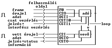
Operation mode of this circuit can be programmed with control words of 15. and 31.
timeslots of the CSTI0 wire, and with control words of 18.
timeslot of the CSTI1 cable. This circuit has 3 control words that are indicated with
marks applied in the handling programm of the ISDN developing card:
MastCtrl1, MastCtrl2, Ús MastCtrl3.
MastCtrl1 MCW1 Master Control Word 1 (15th timeslot of the CSTI0)
| Name | Position | Description | Default
|
|---|
| TstBit | bit7: | - not used | 1
|
| LpBkC16 | bit6: | - Looping back of 16. timeslot
1- in the case of 1 the 16. timeslot of the 2 Mbit/s-os link is looped back,
namely the content of the 16. timeslot of the transmission directed output is
the same as the content of the reception directed input of the link.
This function can only operate, if there is a frame synch, and there is only
one channel looped back in the frame.
0- In the case of 0 the 16. timeslot of the 2 Mbit/s-os link is not looped back.
| 0
|
| TsTBits | bit5-4: | - not used | 11
|
| DebnceCT | bit3-0: | - CAS signalling bit debounce
There can be several signal transitions at ABCD signal cable in the case of
change of statement, especially, when the signal transmission is executed
by a relay, because the relay (electromechanical contacts) osculatories are
bouncing in the case of switching over. Debouncing means, that we filter this
phenomenon at receiving the signal.
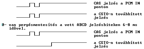
1- there is no debouncing at the received ABCD signal bits..

| 0000 (DCBA)
|
MastCtrl2 MCW2 Master Control Word 2 (31st timeslot of CSTI0)
| Name | Position | Description | default
|
|---|
| TstBit | bit7: | - not used | 1
|
| TstBit | bit6: | - not used | 0
|
| CASignal | bit5: | - Signalling method
- 0 - Channel Associated Signalling (CAS)
The circuit generates and receives CAS multiframe.
- 1 - Common Channel Signalling (CCS)
The circuit does not generate and does not receive CAS multiframe.
. Signals of speech channels are multiplexed by a signal multiplexer
outside from the interface in a HDLC framed signal flow with speed of 64
kbit/s, which is not necessarily the 16. timeslot.
In this operation mode the content of the 16. timeslot of the PCM time frame
arriving to the port of MH98790 DSTi will be forwarded on the 2 Mbit/s link
in the 16. timeslot, in transmitting direction.
In receiving direction the content of 16. timeslot of a 2 Mbit/s link will
occur in the 16. timeslot in the output of the MH89790 DATA ST-BUS OUTPUT /DSTo/.
0?15 timeslots of CSTI1 and CSTO ports (signal input/output) are not used
in this operation mode.
| 0
|
| 8kHz | bit4: | Frequency of the received clock signal, which will be
occur at the C2I output:
| 0
|
| TxAll1 | bit3: | TXAIS (Transmit Alarm Indication Signal) - Sending of AIS
- 0 - normal operation
- 1 - Sending of AIS control signal (consists only ?1?s)
| 0
|
| TxTS16 | bit2: | -TXS16AIS (CAS multikeret AIS)
- 0 - normal operation
- 1 - Sending of CAS multiframe AIS control signal (consists only ?1?s
in CAS multiframe)
| 0
|
| Xctrl | bit1: | -XCTL (External Control)
| 0
|
| Unused | bit0: | -not used | 0
|
MastCtrl3 MCW3 Master Control Word 3 (18th timeslot of CSTI1)
| Name | Position | Description | Default
|
|---|
| TstBit | bit7: | - not used | 0
|
| SIMUX | bit6: | - SIMUX active level: 1
- 0 - normal operation
- 1 - sending back of the result of CRC evaluation in the service code word
| 0
|
| RMLOOP | bit5: | - RMLOOP (Remote loopback)
- 0 - normal operation
- 1 - Test loop at the line side of the PCM interface :

PCM IN signal led to the line input is led back to the PCM OUT output
after regeneration. Besides, circuits realizing the reception interface
processes (synch, multiframe) are operate, too.
| 0
|
| HDB3en | bit4: | - HDB3EN (method of the line coding)
- 0 - line coding is HDB3
- 1 - line coding is AMI
| 0
|
| MAINT | bit3: | - MAINT (Maintenance)
- 0 - in the case of more than 914 CRC errors/sec there is no automatic
resynchronization.
- 1 - in the case of more than 914 CRC errors/sec there is an automatic
resynchronization .
| 0
|
| CRCen | bit2: | - CRCEN (CRC multiframe)
- 0 - circuit does not generate and does not receive CRC multiframe.
- 1 - circuit generates and receives CRC multiframe and makes CRC evaluation.
| 0
|
| DGLOOP | bit1: | - DGLOOP (Digital Loopback)
- 0 - normal operation
- 1 - Test loop on the PCM interface side:

| 0
|
| ReFR | bit0: - REFR | (Force reframe)
- 0 - normal operation
- 1 - initiation of a resynchronization process for a PCM frame
| 0
|
Status bytes of the circuit:
Operation state of the circuit can be read out from the status bytes in the timeslots of
the CSTO cable.
We indicate status information with marks applied in the program of the ISDN developing card.
MSW1 ;Master Status Word 1
Control signals are collected in the MSW1:
| Name: | Position: | Description
|
|---|
| TermFrmAqui | bit7: | (4.12) equivalent of LOF (Loss Of Frame alignment)
control signal
0 - frame synch exists
1 - none frame synchs
|
| MultFrmAqui | bit6: | (4.12) equivalent of LOMF (Loss Of MultiFrame)
control signal
0 - multiframe synch exists
1 - none multiframe synchs
|
| TFrErr | bit5: | Frame synch errors:
change of state in the bit. 16 frame synchronous errors are occurred.
|
| Slip | bit4: | - SLIP
Change of state in the bit: slip occurred.
|
| All1'sLost | bit3: | (4.12) equivalent of AIS (Alarm Indication Signal)
control signal
0 - no AIS
1 - circuit receives AIS
|
| Ts161'slost | bit2: | (4.12) equivalent of MAIS (Multiframe Alarm Indication
Signal) control signal
0 - no MAIS
1 - circuit receives MAIS
|
| ExtStat | bit1: | - (External Status)
Logical level of the signal at the status port of the circuit.
|
| | bit0: | - not used.
|
MSW2 ;Master Status Word 2
Status information according to the CRC multiframe is collected in the MSW2.
| Name | Position | Description
|
|---|
| | bit7: | - SI2 (Remote SMF2)
0 - correct
1 - wrong
|
| | bit6: | - SI1 (Remote SMF1)
0 - correct
1 - wrong
|
| | bit5: | - not used.
|
| | bit4: | - not used.
|
| | bit3: | - not used.
|
| | bit2: | - CRCREF
0 - normal CRC multiframe synch
1 - frame synch was not followed by a CRC multiframe synch within 8 ms.
|
| | bit1: | - -CRCSYNC (CRC multikeret)
0 - exists
1 - none
|
| | bit0: | - FRMPHASE
9th bit of the PSW
|
--------------------------------------------------------------------------
PSW ;Phase Status Word
The transmission phase of PCM frame:
| bit7-3: - -TXSTC
transmission timeslot position
|
| bit2-0: - -TXBTC
transmission bit position
--------------------------------------------------------------------------
CEC ;CRC Error Counter
|
| bit7-0: - CERC
Number of CRC errors
--------------------------------------------------------------------------
FrByte - frame synchronous code word (FAS)(I/O - transmitted, received)
NFrByte - service code word (NFAS)
MFrByte - CAS multiframe service code word (MFAS)
|


