Interface testers are measuring gadgets applicable for testing of operating abilities of standard interfaces of the telecommunication hierarchy. Some of the applications are the following:
- Frame monitoring
- Framed (unframed) error measuring between point-point
- Multiplexer/demultiplex test
- Digital switching field tests
- Phase jitter measures
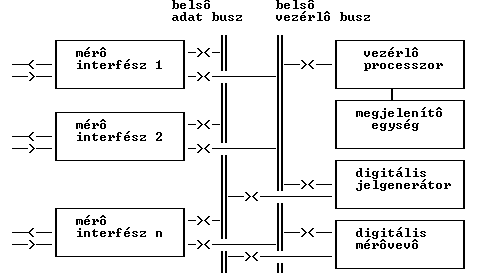
General blocking draft of the interface tester can be shown on the following figure:


In the interface tester the functional units of the measuring gadget are strung to the internal data and the control bus:
- Measuring interfaces (PCM, 64k, RS-232, V-11 etc.) for the connection to the examinable interface. The measuring interface is functionally the same as the interfaces connecting together the elements of the telecommunication hierarchy, but it has usually better electrical parameters. Its main functions are:
- Framing/frame decoding
- Line coding/decoding
- Digital signal generator end digital measuring receiver for the generation of a testing signal and for processing the tested signals.
These functions can be realized in many cases by a program running on DSP.
- Control processor (computer) with built-in keyboard and display.
- Communication interface for maintaining a connection with the external world (remote control, reading out measuring results).
Traffic of the measuring signals can be transacted in an internal time-sharing databus (e.g. ST-bus) between the measuring interfaces, the signal generator and the measuring receiver. Traffic of the databus is controlled by the control processor together with the measuring task. The bus provides, that in case of the framed signals the measuring signal can be put into one, or more frames, and to obtain from them (drop-insert operation mode). Control of the measuring interfaces, signal generator, measuring receivers can be made by the control processor through the internal control bus (microprocessor bus).
Main characteristics of the interface testers::
- Multi interface ability: the tester has more measuring interfaces (e.g. V.24/RS232C, V.11/X.24, V.35, V.36/RS449, G.703 co-dir, G.703 (2048/704 kbit/s), thus we can access to more points of the telecommunication network.
- DTE/DCE (NT/TE) ability: the tester is able both to the emulation of the data terminal equipment (terminal), and to the transmission equipment (modern).
- Programmable electrical parameters, line coding - the mode of line coding, the signal level and the connection impedance can be set on the measuring interface.
In case of giving a line coded signal it is possible to put in coding errors, coding offences.
- Unframed generator and measuring receiver ability - signal of the measuring signal generator can arrive to the output without framing, and the signal arriving to the input can get to the digital measuring receiver without decoding.
- Framed generator ability
- drop-insert connection mode
- inserting the measuring signal one, or more time-gap of the frame (nx64 kbit/s test)
- Programmability of frame elements
In case of PCM frame there can be programmed:
- Frame synchronous codeword
- CAS multiframe synchronous codeword
- Codewords, that are not used for measurement, and forwarded into information and signal time-gaps
In case of asynchronous frame can be programmed:
- data transmission speed
- number of information bits
- parity bit
- number of stop bits
- Framed measuring receiver ability
- trough-connection access mode
- automatic recognition of frame format
- raising of the measuring signal from one, or more(nx64 kbit/s test) time-gap of the frame
- Forwarding the content of the frame elements to the digital measuring receiver
Frame elements can be taken out in case of a PCM frame:
- Frame synchronous codeword
- Servo codeword
- CRC-4 multiframe
- CAS multiframe synchronous codeword
- displaying and forwarding control signals of the interface


