Application:
LAN/MAN interface is used widespread for connecting various LAN/MAN network elements (terminals, servers, bridges, etc.).
This interface has numerous wired (CSMA/CD, Token ring, FDDI, ...) and wireless (WLAN, Wi-Fi) physical realizations. We will only review in details the CSMA/CD and according to the identifier of the relating standard, the 802.3 (Ethernet) in the tutorial.
Elements of the recommendation, standard describing the interface:
IEEE 802.3 wired physical layer
IEEE 802.11 wireless physical layer
IEEE 802.1 management
Services:
The interface provides the following services to the higher layers:
The notations of the two sides and internal sublayers of the interface in the IEEE 802.3 standard
           10BASE:
                ---+    +-+-----PHY-------+     ||
                   |    | |               |     ||transmission
               MAC |----|P|               |-----||medium
                   |    |L|      PMA      |     ||
                   |    |S|               |     ||
                ---+    +-+---------------+  |
                          |                  |
                         AUI                MDI


           100BASE, 1000BASE:

                ---+    +-+-----PHY-------+     ||
                   |    | |               |     ||transmission
               MAC |----|R|               |-----||medium
                   |    |S| PCS, PMA, PMD |     ||
                   |    | |               |     ||
                ---+    +-+---------------+  |
                          |                  |
                         MII                MDI
Legend:
The interface was realized at several transmission media:
| Medium | Notation according to standard | Remarks |
|---|---|---|
| thick coaxial cable | ..BASE5 | thick ethernet |
| thin 50 ohm coaxial cable | ..BASE2 | thin ethernet |
| twisted pair | ..BASET | twisted-pair: UTP - unshielded twisted pair STP - shielded twisted pair TPE - twisted pair ethernet |
| optical fibre | ..BASEF | |
| wireless | 802.11a/b/g/n |
The word BASE relates to the base band signal transmission.
Pins of the jack: RJ-45  10BASE-T/100BASE-TX  (EIA/TIA 568-A/B: Commercial Building Wiring Standard)

                 -A     -B
             1   Tx+    Rx+
             2   Tx-    Rx-
             3   Rx+    Tx+
             4   nc     nc
             5   nc     nc
             6   Rx-    Tx-
             7   nc     nc
             8   nc     nc
Interface topology:
| topology | notation according to standard |
|---|---|
| bus | 10BASE-5, 10BASE-2 |
| star | 10BASE-T, 100BASE-T |
| ring |
Several bit rates:
| bit rate | Notation according to standard |
|---|---|
| 10 Mbit/s | 10BASE |
| 100 Mbit/s | 100BASE |
| 10/100 Mbit/s | 10/100BASE |
| 1000 Mbit/s | 1000BASE |
Signal levels, line coding:
| Notation according to standard | Signal level | Cable | Line coding | Remarks |
|---|---|---|---|---|
| 10BASE-2 | 0V ... -2V | coaxial | Manchester | "thick" ethernet |
| 10BASE-5 | 0V ... -2V | coaxial | Manchester | "thin" ethernet Baud rate: 20 MBaud |
| 10BASE-T | +/-2.5V (2.2V...2.8V) | 2 twisted pairs | Manchester | |
| 100BASE-TX | 0V...+/-1V | 2 twisted pairs (Cat 5) | 4B/5B, MLT-3 | "fast" ethernet, Input: MII bus Baud rate: 125 MBaud |
| 100BASE-FX | optical fibre | 4B/5B, NRZI | "fast" ethernet, Input: MII bus | |
| 100BASE-T4 | 3.5V +/-10% | 4 twisted pairs (Cat 3,4,5) | 8B/6T | |
| 100BASE-T2 | 1.81V +/-0.5dB | 2 twisted pairs (Cat 3) | not used | |
| 1000BASE-SX | Two optical fibres (Short wave length, multimode) | block, 8B/10B | GigaBit Ethernet (GBE) | |
| 1000BASE-LX | Two optical fibres (Long wave length, mono/multimode) | block, 8B/10B | GigaBit Ethernet (GBE) | |
| 1000BASE-CX | ECL (3...1.1V) | 4 twisted pairs (150 Ohm) length: 0.1...25m baud rate: 1250 MBaud | block, 8B/10B | GigaBit Ethernet |
We illustrate the signal at the data cables with oscillograms.
10BASE-5 line signal oscillogram:

Lower part of the diagram shows the beginning of an Ethernet frame and its upper part shows its reached detail (SFD). If there are no any packets to be forwarded, then there is no signal on the interface. Line coding is Manchester (-2V -> 0V signal transmission corresponds to the binary 0, and the 0V -> -2V signal transmission corresponds to the binary 1.
10BASE-T oscillogram:
We can measure a signal among the strings of the pairs, which is similar to the line signal of 10BASE-5
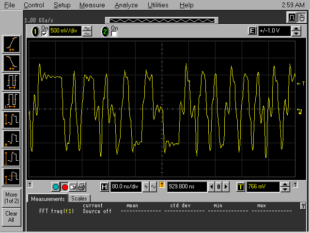
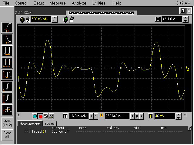
100BASE-TX line signal oscillograms:
Time diagram details:
On the following figure we can see a typical 100BASE-TX signal detail. This signal has three levels, the signal amplitude is 1V. on the signal detail oscillations caused by the reflexion between the cable and the transceivers. However it cannot be seen on the figure, there is a signal between the two packages. It also cannot be seen, but the signal rate is 125 MBauds, which means that there are 10 line symbols located horizontally between two raster lines.


Illustration of MLT-3 coding (besides 1 line symbol/raster horizontal diversion):
  source series: 1 1 1 1 1 1 1 1 1 1

  line series: 0 1 0-1 0 1 0-1 0 1

Illustration of MLT-3 coding (besides 2 line symbol/raster horizontal diversion):


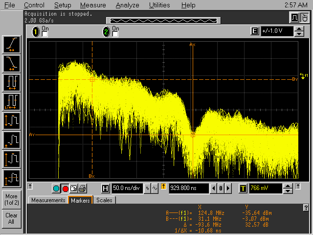
Spectrum of the signal:

We find the first minimum at the baud rate (125 MHz). Most of the energy of signal falls to the 0...125/4=31.25 MHz band. It is the result of the MLT-3 coding.
Wired interface frame formats (Layer1)
          bytes
              +--------------------------------+
            7 | Preamble                       |   7 x  10101010  Syncronizing receiver's clock to the sender
              +--------------------------------+
            1 | SFD Start of Frame Delimiter   |        10101011  begining of the frame
              +================================+
              | D  basic MAC Data field        |
      60-1514 |    tagged MAC Data field       |
              |                                |
              +================================+
            4 | Frame Check Sequence           |
              +--------------------------------+

Interface processes, remote feeding

Test and maintenance functions
The IEEE 802.11 WLAN interfaceMost important elements of the 802.11 standard
IEEE 802.11 standard family has an important role in establishment of wireless local data transmission networks. Several members of this family are used currently in the establishment of WLAN networks.
| Name | Year of acceptance | Frequency - GHz | Modulation | Bit rate - Mbps | Remarks |
|---|---|---|---|---|---|
| 802.11 | 1997 | 2.4 or IR | PSK (FHSS or DSSS) | 2, 1 | - |
| 802.11a | 1999 | 5 | OFDM | 54 (24, 12, 6) | wireless ATM |
| 802.11b | 1999 | 2.4 | CCK (DSSS) | 11 (5.5, 2, 1) | wireless Ethernet |
| 802.11g | 2003 | 2.4 | OFDM | 20-54 | - |
Resolving the abbreviations:
Of course, range depends on the actual place, or on modulations used for the individual standards, in case of B and G standards compatible backwards together with it, it can be within a building 30-50 metres, and outside the building it can be 1 kilometer (if we can see the AP). In case of the A standard the range is a bit smaller. Note, that for wireless communication with small range, and small energy (but with fast rate, compared to that) the Bluetooth (IEEE 802.15), and for large ranged connections in urban environment the WiMax (IEEE 802.16) is used.
It could be interesting, so we will mention here further two members of the 802.11 family:
We can study on the figure below the channel division used in the most prevalent WLAN-standard, the 802.11g. We can see, that channels may overlap each other, and they have a broadness of 22 MHz. Bearers are to 5 MHz from each other, thus a channel located in the centre of the frequency domain can interfere with 8 other at the most. Arrangement of the 14th channel does not follow this regularity. We just note, that not all the channels are in use in all geographic regions. Besides, selection of aggregation of non-interfering channels is not the same in the individual regions. (Spectral details indicated with a continuous line on the figure demonstrate the selection valid in the USA and China.)

Protocol Structure - WLAN: Wireless LAN by IEEE 802.11, 802.11a, 802.11b,802.11g, 802.11n
801.11 protocol family MAC frame structure:
|
2 |
2 |
6 |
6 |
6 |
2 |
6 |
0-2312 |
4 |
|
Frame Control |
Duration |
Address 1 |
Address 2 |
Address 3 |
Seq |
Address 4 |
Data |
Check sum |
|
2 |
2 |
4 |
1 |
1 |
1 |
1 |
1 |
1 |
1 |
1 |
|
Version |
Type |
Subtype |
To DS |
From DS |
MF |
Retry |
Pwr |
More |
W |
O |
"6.1.4 MSDU format This standard is part of the IEEE 802 family of LAN standards, and as such all MSDUs are LLC PDUs as defined in ISO/IEC 8802-2: 1998. In order to achieve interoperability, implementers are recommended to apply the procedures described in ISO/IEC Technical Report 11802-5:1997(E) (previously known as IEEE Std 802.1H-1997 [B13]), along with a selective translation table (STT) that handles a few specific network protocols, with specific attention to the operations required when passing MSDUs to or from LANs o r operating system components that use the Ethernet frame format. Note that such translations may be required in a non-AP STA."